Review

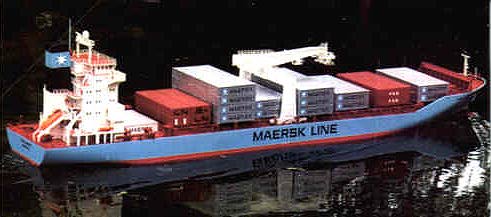
Well, this is one for the big boys - at 1600mm long and with a beam of 318mm, it is a large model, but despite the size, not a difficult model to build; and it is very manoeuvrable as well as graceful on the water. One major worry I had when taking on this project was how to transport the completed model, so I gave this area a lot of planning before starting on the build.
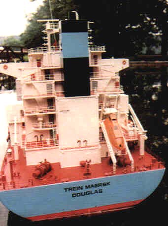
The prototype The 'T' Class container feeder ship that this model is based on, was constructed for the Maersk Line in 1990 by the Tsoneishi Shipbuilding Co. in Japan. The vessel is used as a feeder ship and container vessel, to countries and ports where no container terminals are based. This accounts for the full size container crane with extended reach to enable the containers to be unloaded direct on to transport or dockside. For this reason she is fitted with very powerful bow and stern thrusters, for docking unaided in small ports where tugs powerful enough to handle such a ship are not always available. The keel of the ship was laid on 13th October 1989 and she was launched on 24th January 1990, then finally delivered to her owners on 15th May 1990. She was registered in Douglas, Isle of Man; as are many of the Maersk ships working from the United Kingdom. At present (1996) she is operating from Hamburg, Felixstowe to Mexico and carries a crew of 20 persons plus a Suez crew of six when required.
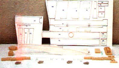
First thoughts I applied a slightly different approach to the start of this model, and that was to firstly remove from the kit box all five trays of fittings, the tray plans, the instruction book, and lastly, the model plans. The latter were fixed to the workshop walls with Blu-tack, Then using sticky tape along one edge the tray plans were attached to their respective trays, and finally while studying the build using both instruction book and plans, I cleaned the fittings ready for use. There are two things to note if this method is to be utilised.
After the planning it was now time to start the build, so having placed all the fitting trays to one side I again delved into the kit box. This time I removed the GRP hull and deck, the propeller shaft, the plywood with the bulkheads printed on, and the strips of wood for the deck beams.
Stand Provided in the kit are outline drawings of both cradles to help construct a stand. However because of the amount of flat area on the bottom of the hull I decided that a stand was not really necessary, and throughout the build, I just placed the hull on a cloth covered bench.
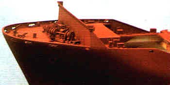
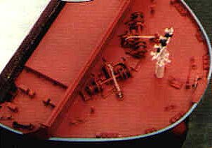
Hull Having washed the hull and smoothed it down using a dry abrasive I cut out the two bulkheads from the plywood and fixed them in place as per instructions. Next three lengths of square stripwood were fitted between these bulkheads, one in the centre and the others along both sides. The space between these strips was filled in with lead shot, held in place with resin. Using 4mm thick plywood I made a base that fitted between the bulkheads and covered all the stripwood plus lead. This base was held in place with screws. During the planning stage I had decided to use an M.FA. Torpedo 800 motor for the main drive, and although a 12v motor, it was my intention to operate it using a 6v battery, a combination that has worked successfully for me in the past. Also a working bow thruster was to be installed and this would be operated from the same battery, but through a separate speed controller. When the propeller tube had been made and fitted I connected the motor to the shaft via an S.H.G. heavy-duty coupling, and when all aligned they were fixed in situ. The instruction book gives two methods in which the rudder can be attached - I chose method one, which gives an exact scale appearance. Even though the whole of the rudder does not move using this method, the working bow-thruster will compensate. Moulded into the hull are the positions for both forward and aft bow-thrusters, however I removed the forward positions as to allow for the width of tube on the working bow-thruster I had to reposition it approximately 25mm further aft. The aft moulding was left in and later painted to simulate the thruster tube. When the installation of the forward bow-thruster had been completed I glued the deck beams around the top edge of the hull, allowing for the thickness of the deck.
Deck The GRP deck has seven raised hatch mouldings and the builder has the choice of removing the tops from as many, or as few as desired to gain access to the interior. I chose to remove Nos. 2, 3, 5, 7 and 8. Also, by taking the base area dimensions of the superstructure from the plan and marking it in the correct position on the deck, this area too was removed. I next trimmed the deck to fit neatly to the hull before gluing it in place using De-Luxe Materials Super Crylic glue. I removed the sheets of 1mm thick printed plastic card that contains the foredeck and hatch covers, from the box, then having glued in place the beams and supports for the foredeck I cut the deck from the sheet. When the bulkhead between the two decks had been fitted I trimmed, then glued the foredeck in place. A note of interest is the new format the manufacturer has adopted in the instruction book, this being digital pictures of each stage of the build accompanied by the text. I thought this helped to simplify the build. At this point that I gave the hull two coats of red primer paint using acrylic spray cans. When the paint had dried I progressed onto the hatch covers and these were removed from the plastic sheets using a sharp knife, but flrstly I checked if there was any discrepancy in size between the hatch and its cover; and if satisfied they were removed. A 4mm plastic strip is glued around the edges of each cover; but to the removable covers I glued strips of square balsawood to the underside around the hold opening. This is to help lock the covers in place more securely. The plastic sheet that contained all the printed parts for the breakwater was removed from the box and cut out Once assembled as per instructions it was glued to the foredeck.
Intermediate Painting Stage Although I do read and study the kit instruction book, I do not always follow the construction stages as set down by the manufacturer. If I have an idea to make what is I think an easier build, I adopt it and hopefully pass it on to future builders of this kit. My idea this time was to have the deck and deck fittings all the same colour, and this along with the following method of build, dramatically simplifies the construction without jeopardising the end result. At this point you start to benefit from preparing the fittings earlier. All you have to do is remove them from the tray and place them onto card containing double sided tape ready for spraying. To make things easier I placed them onto the card as they would be positioned on the deck, and each hatch area was handled separately because of the amount of fittings. Starting from the bow each fitting required was painted red primer (the same colour as the hull) and glued in-situ onto the deck. Then when I had progressed aft and completed the area around No.2 hatch, the decks, up to this point, were sprayed again using red primer. Now because of the railings that need to be installed along the edge of both deck sides it was going to be easier at this point to paint the blue colour around the upper part of the hull, so this was done. While I was in the painting mode I sprayed all the hatch covers with a dark grey paint. When the blue paint had dried I added the red waterline, however I did not paint this on, but used strips of self-adhesive Solarflilm to achieve this line. A friend of mine who builds model aircraft passed on the following idea. Firstly lay the film out over a cutting mat and peel the backing off all four corners to hold the film down. Then determine the thickness of the strip required and find a piece of wood that matches the measurement in width. At one end of the wood, tape two sharp knife blades, one to either side. Now this means the distance the blades are apart is the thickness the strip requires to be. Using a steel rule as a guide cut along the length of the Solarfilm to produce a perfectly parallel strip. Cut as many as is required to add the line around the hull and men remove the backing and fix in place. Alter adding the decals which are all supplied in me kit, the whole of the outer hull area was sprayed with enamel satin varnish paint It was now back to adding the fittings to the deck, and as I had done before, each hatch area at a time was done. All holes for the stanchions had to be drilled into the deck, with being GRP, and the stanchions and railings were painted before being glued in place. When I had completed adding the fittings to the deck, the surrounding area was masked off ,and the deck spray-painted with red primer. I built, painted grey, and fitted the platform on the front of the foredeck, plus the top rails, the crane runs, glueing them in place before finally spraying the whole of the deck area with enamel satin varnish paint. The hull and deck were now complete, and I have to say by using this method, construction was not difficult and the end result was very good. Radio et al With the amount of access area on the model I left the installation of the radio gear until now. A three channel radio set was to be used, one channel for the rudder; one for the bow-thruster and the one for me main motor. I chose an Electronize Speed Controller Type 43HX for the main motor and an Electronize 43X Speed Controller for the bow-thruster motor. When they had all been installed, the batteries were fitted and the units were successfully tested.
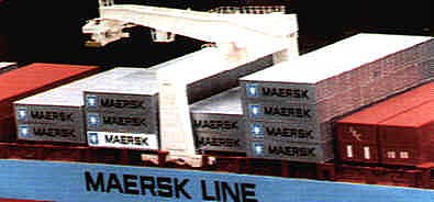
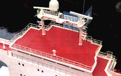
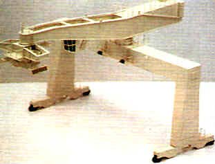
Above Deck As stated at the beginning of the article I gave transportation of the model a lot of thought and decided that any item that protruded above the breakwater would be made removable, so the hull could be placed into a box that measured no more than 270mm in height. This would mean that owners of smaller vehicles could fit this box to a roof-rack, allowing the remainder of the model parts to be boxed and placed inside the vehicle. All the parts required for the crane were assembled and I split this build into two sections, the base and then the jib. Starting with the base I cut the main structure parts from the plastic sheet and assembled them. To the finished structure I added the resin bases, the cast metal runners, the platforms and the railings before placing to one side, awaiting painting. The jib contains a lot more detail than the base, but again in the instruction book there are step-by-step digital pictures which really do help simplify the build. After the completion of both halves they were joined together and painted, firstly with white primer, then with a light beige colour, and lastiy sprayed with satin varnish. I next built and painted the forward mast, but because it stands higher than the breakwater I made it removable by drilling a hole in its base and inserting a piece of brass rod. I then drilled a hole in the deck where it was to be positioned and fitted it in place. Using this method means that it can be removed and replaced whenever required. Containers All the GRP mouldings for the containers were removed from the kit box and placed onto the model. Even though I rearranged them a few times I could not help but think it looked too cluttered, and also when sailing they would certainly catch the wind. I therefore contacted Dean's Marine to see if there were any alternative methods. Dean's stated that the kit can be purchased without the grp container mouldings, giving quite a saving in the kit price, and alternatively single rows of moulded containers can be purchased separately, or rubber moulds and powder can be bought to make your own containers. Having now got all the details I planned my container arrangement. No.1 hatch remained uncovered because I did not want to hide the deck details around this area. No.2 hatch has two rows of 40ft containers, which I painted silver and added the MAERSK lettering and motif to the sides (these are supplied in the kit). No 3 hatch has two rows of 4Oft and these I painted in red primer. No.4 was made the same as No.2. No.5 has a GRP moulding of three rows of 40ft containers which were painted silver and the lettering added. No.6 is a GRP moulding of two rows of 40ft containers, agan painted silver and lettering added. No.7 hatch has the large four rows of 40ft container GRP mouldings, which too was painted silver and the lettering attached. No. 8 hatch has two GRP mouldings of 20 containers which I painted red primer. The GRP mouldings in the kit which I did not use were returned to Dean's Marine in exchange for rubber moulds and some powder mix, and with this I moulded and constructed a row of containers to cover No.9 hatch. There are instructions that accompany these parts to help with the making of these moulds. This is how I produced mine. The powder is just mixed with water - volume is indicated in the instructions. After mixing the solution it was worked into the moulds and left to dry for approximately four hours. One thing I learnt was that the warmer the water used the quicker the setting time. Having produced all the mouldings required I started to assemble them. A piece of 1mm thick plastic card is used for the base and this is cut to size. Firstly glue one side moulding to the base followed by the end mouldings along the other edges, and finally glue the other side moulding in place. Another piece of 1mm thick plastic card, which will be the top, is cut to the same dimensions as the base and onto this the width of each container is marked. Using a cutter, a groove is formed along these marked lines which gives the impression of individual containers. Finally the top is glued on and the unit painted silver before adding the lettering. One last job on the GRP container mouldings was to place them upside down on the work bench and to the bottom edge of each I glued strips of 5mm square lengths of balsawood; this was to form a bigger area for gluing them to the hatch covers. Again note that the two container mouldings fixed to the model are not removable, these being on No.4 and No.6 hatches, do not exceed the height of the breakwater.
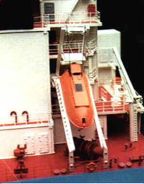
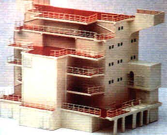
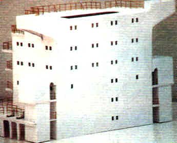
Superstructure Now it was time to construct the superstructure. The remainder of the kit parts were removed from the box and placed on the bench. The empty box was then cut up into squares and used for either mixing glue on, or placing the fittings on when spraying, so you see a good modeller has a use for nearly everything. Each part that was required for the superstructure was first checked, then cut from the printed plastic sheets. All the windows in the front and side sections were removed and later glazed. The assembly was quite rapid using Plastic Magic glue and a miniature try square to keep things correct. Again the digital pictures in the instruction book are very good. Once the basic structure, plus the decks had been completed, I constructed the main engine room intakes and joined them to the superstructure. All the windows in the front and sides of the bridge parts were removed, then the bridge was constructed. I did not add the bridge to the superstructure until later because the windows would have to be glazed after it had been painted. The brass etched stanchions and railings were added next and they were cut to size, bent to shape, and using a soldering iron, heat sunk in place. I then started to attach all the detail such as vents, doors and drain pipes to the superstructure and when completed the structure was painted, first white primer and then with a light beige colour, the same as the crane. Once dry, the decks were all painted red primer. After the funnel had been constructed and painted it was glued in place on the superstructure. The inner doors were painted grey and glued in place, as were the steps between decks after being painted beige. Using Humbrol Clear-Fix I glared the windows in the superstructure, excluding the bridge windows. These were glazed with clear plastic after the bridge and deck had been painted. I glued the bridge to the superstructure using Super Crylic to avoid the windows hazing . Masking off the bridge windows, the whole of the superstructure was sprayed with satin varnish, and left to dry. I decided to make the lifeboat, its launching platform and also the crane on the starboard side removable. The launching platform consists of seven cast metal parts, two platforms cut from plastic card and railing made from stretch brass wire. This was constructed as per instructions with no difficulty, and to the base of the two down legs, I drilled and inserted some brass wire. Two holes were drilled into the deck where the two legs seated and this then allowed the launching platform to be removable. The platform was painted the same colour as the superstructure and after painting the lifeboat orange, both parts were glued together. After assembling the starboard crane it too was painted the same colour as the superstructure, and a hole was drilled into the deck to accommodate it. The main mast which is positioned on the bridge roof, again consists of several cast metal parts, and although there was not any mention of this item in the instruction book, there is enough information on the plan and in the photographs retrieved from the kit box lid to construct a detailed item. Once completed it was pegged and glued into place and the restraining wires were made from stretch brass wire and attached.
Ballasting The model was now complete, and it was time to assemble the paddling pool so the ballasting stage could be achieved. Onto the water went the hull section and into this I placed two 5 kilo scale weights and the 6v 10amp battery. They were rearranged in various positions along the base between the bulkheads until the ballast as well as the trim, were nearly correct. One by one the containers were placed on and finally the superstructure, then after a couple more slight movements of the weights I was happy with the ballasting. A line was drawn around the weights and battery before they were removed, then lengths of 10mm square strips of wood were glued along the outside of these lines to hold the items in place. The on/off switch for the radio receiver was placed inside No.7 hatch, as this is quite easy to remove for access.
Trials Now it was time for the model's first fully operational sail so it was off to my local club's boating pond at the Windermere Steamboat Museum to see how it would perform. I took along a small portable table, which was placed near the edge of the pond and onto it I put all the containers, superstructure and other parts that are removable, then the hull was removed from the box and placed onto the water. Both weights were added along with the battery and after connecting up the battery, everything was tested before fitting the containers and superstructure. Now one thing I noticed was how smaller it appeared sitting there on the water, when in my workshop it seemed a lot larger! Well it was now time to bring it into life, and that l did with a gentle forward movement of the motor control stick on the transmitter. What response, firstly with left full rudder; then right full rudder along with forward and reverse, and to really make it manoeuvrable the how-thruster was activated. All this took place on a Saturday and next day was our club's monthly fun regatta, so I took along this model, as well as my steam boat. At the end of the fun event I placed this model onto the water to test it around a set course, and although it was not difficult, I sailed a clear round, showing to all the onlookers, admirers and myself what a graceful mover it is, for such a large model. To summarise this build, I would say it was not at all difficult, and making most of the upper deck parts removable considerably helps with the transportation, but the icing on the cake comes when upon the water, being steered around a regatta course.
ALL enquiries regarding this magazine should be made to Nexus Media, NOT TO US. This page was last edited on: 8 November 1999 |